| Email John |
| Last update
12/09/2010
|
Reg Guide 1.97 At TMI Unit 1

Just like the Generals who tend to prepare to fight the last war, the NRC went absolutely overboard with new regulations to prevent another TMI-type accident. I'm sure they were 100% successful. But in the process, in my opinion, they made many aspects of plant operation much more difficult, potentially error-prone and thus potentially a little less safe. And in the process they caused utilities all over the country to waste billions.
They published something called REG GUIDE 1.97 Instrumentation for Light-Water-Cooled Nuclear Power Plants to Assess Plant Conditions During and Following an Accident and associated NuRegs. This massive tome detailed all the changes that would have to be made to operating nuclear plants in the area of instrumentation and controls.
The basis for this document were sound. Most every radiation monitoring instrument on the Island pegged at full scale indication very early in the incident when the first fuel cladding failures happened. Neither the operators nor the government were equipped to get even orders-of-magnitude estimations of radiation levels, either inside the plant or off-site. The result was that in the hysteria of the moment some really bad rumors were released as fact. Rumors such as a radioactive cloud headed toward Harrisburg.
The reason for this over-ranging of the instrument is that during normal operations, radiation levels inside the plant and radioactivity in the discharge air and water streams are so low as to be essentially background. Like dropping a steam roller on a laboratory balance!
The problem was that the government over-reacted and made the situation as bad or worse, only in the other direction. They specified instruments with such high ranges that even a typical accident wouldn't move the pointer off zero. One wag suggested that if the entire core was removed from the reactor and somehow transported to the main reactor vent, the associated high range monitor MIGHT just barely see it.
Silly as those specs were, they were the law and so TMI Unit 1 had to do 'em. They contracted with Victoreen Instrument Company to build the radiation monitors and contracted with me to install and calibrate them.
The problem was that Victoreen (and pretty much nobody outside certain weapons programs) had any experience with radiation and radioactive material concentrations of the levels we were to deal with. Whereas a normal gas monitor that monitors the reactor building vent measures radioactive gas concentrations down in the micro- and pico-currie pre CC level, the specs for the post-accident monitors called for the ability to measure Curies per cc!
Lots of strange things happen at those levels. Lead shielding gets stimulated to produce Bremsstrahlung radiation and becomes a source of radiation to the detector instead of shielding it. Charge gets deposited into electronic components and causes them to mis-fire. The total integrate dose (TID) rating for semiconductors can be exceeded in minutes. Physically tiny quantities of radioactive noble gases absorb onto and into materials, making them intense emitters of radiation.
I had some experience in the area and I knew people on the weapons side that had a lot of experience in these areas. I did some calculations and simulations (on an Osborne 1 CP/M computer!) and was back-checked by these other people and quickly realized that the instruments would have to actually be subjected to these high levels of radioactive gases and radiation fields to ensure that the extrapolated design would work.
We contracted with the Battelle Memorial Institute which operated several high radiation facilities for the DOE around the country, for the use of their "hot cells" and other facilities. Our first runs indicated that the extrapolated designs were grossly wrong for the post-accident environment so a simple calibration project turned into a major re-design project. We ended up not only re-designing the monitors but also conducting the first ever full scale calibration of these high radiation monitors. Photos and descriptions of this effort follow.
In the end this was wasted effort and money. To their credit, over the years the NRC has gradually backed off much of their over-reaction. For the post-accident radiation monitoring systems, that means that much of the system has been removed and the remainder re-designed to function at more reasonable radiation levels.
NOTE: As I'm in the process of moving and most of my records are in boxes somewhere, much of the information on these pages is coming from almost 30 year old memory. it's conceivable that some errors could creep in. As I uncover my records I'll fact-check for accuracy. meanwhile, if you find an error, please click the "email" button on the left and send me an email telling me about it.
All photos were taken in the 1981-82 time frame. I'm documenting ancient history here :-)
The main steam lines coming from the reactor building, lines that do not carry radioactive steam, were mandated to be monitored. This was quite a challenging task, as the steam line is made of steel several inches thick and carries steam at about 900 psi and 600 degrees F.
Victoreen decided to design an external monitor that would sit up against the rigid pipe insulation and look at radiation that penetrated the pipe and insulation. Because it fit the contour of the steam pipe and because of its resemblence to a snow plow, that's what they were called. "Snow Plow" detectors.

Based on measurements and calculations, we set the detector back about 4 inches and inserted a lead plug into the opening. In this plug was drilled a 3/8 diameter beam port. This plug now restricted the detector's view of the pipe to only that radiation that bore straight down the 3/8" hole.
The piece hanging at an angle is positioned over the plug and is a "graded shield". As I mentioned before, lead can be excited by energetic radiation to give off Bremsstrahlung X-rays. The detector detects these X-rays just like any other radiation. Not allowing for lead fluorescence was a major design flaw.

Cadmium, in turn, emits fluorescent X-rays at a much lower energy. Copper happens to have a huge absorption cross-section for those X-rays. What fluorescent X-rays that copper produce are too low of energy to affect the detector.
The sheet hanging askance is a sandwich of thin cadmium and copper sheeting. The inside of the detector chamber is lined with the same material.
This "Graded Shielding" is standard practice in the gamma spectroscopy lab but generally hadn't made it out to the field at that time.
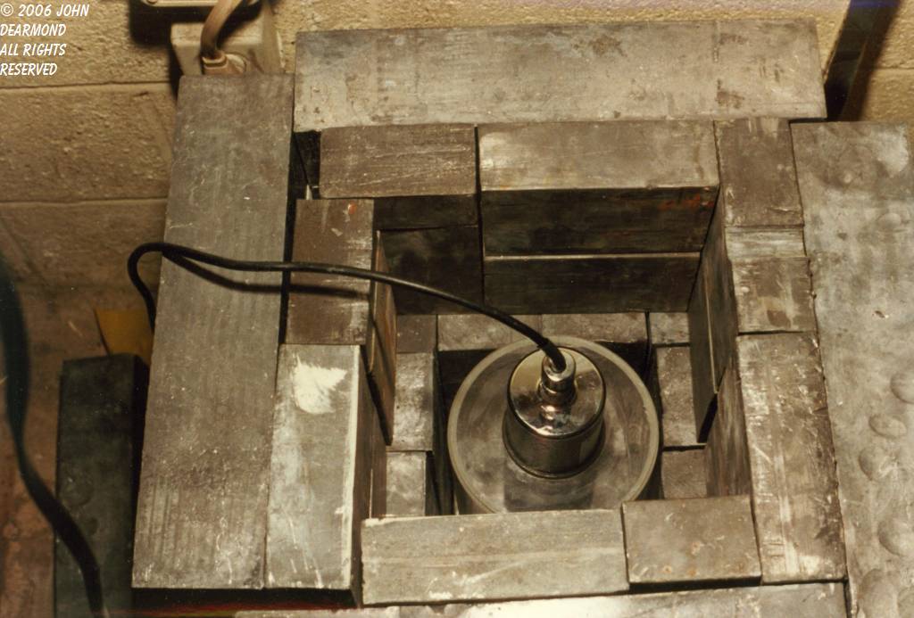
The radiation is delivered by the plastic beaker in the foreground that contains Kr-85 gas. Lead bricks around the beaker serve to collimate the gamma beam being emitted.


One of the required channels of post-accident monitors involved monitoring the ambient radiation inside the containment building. This put a severe demand on the detector, as it had to withstand both very intense radiation and fairly high pressure steam in the post-accident environment. This same measurement could be done - and was done at TMI-2 - from outside the building but like they say, there's the right way, the wrong way and the government way.
Victoreen designed this detector around one of their normal low range ambient radiation monitors. This is a rugged and proven detector so that wasn't a bad choice. The detector was put inside a hermetically sealed shield chamber that attenuated the radiation and protected the unit from steam. Unfortunately this sort of measurement didn't scale up well so when we subjected the detector to the specified post-accident radiation, it pegged full scale far too soon.
We had to characterize the detector and to do that we had to generate the same sort of very high radiation field that might be expected during an accident. Fortunately Battelle had what we needed. On the site was a 10 story tall open building that had been used to assemble nuclear rocket motors. It had a crane in the ceiling that reached to the floor.
We decided to bring a large radiation source to the hangar arranged to shine a gamma ray beam upward. We hung the detector from the crane along with a reference instrument and again used the inverse square law to vary the dose to the detector by running it up and down.
The source was a 10,000 Ci Co-60 source assembled in a spent fuel shipping cask from metal pellets. This is much hotter than any spent fuel so we surrounded the cask with lead loaded bricks.


Condenser Vacuum Pump Monitor
Yet another monitor is the Condenser vacuum pump monitor. The condenser sits under the turbine and uses river water to condense the steam from the turbine back to water. The condenser operates in a vacuum to reduce windage losses in the turbine and to make the cycle a bit more efficient.
This vacuum is created by the condenser vacuum pump, a combination of steam jet ejectors and mechanical roots-type pumps. The pumps exhaust to the atmosphere.
Steam in a PWR is non-radioactive. Nonetheless the government mandated that it have a high range post-accident monitor to account for a couple of barely credible accident scenarios in which reactor water could get to the secondary side.
Again, the formulae used at low radiation levels didn't scale so we had a lot of work to do on this monitor. We greatly reduced the volume of the detector chamber and partially shielded the detector. Unfortunately I didn't get "after" photos of this particular unit


Battelle scientists were investigating failed fuel elements from GPU's other plant, Oyster Creek. The photo shows a failed fuel pin. This pin contains pellets of uranium dioxide. While the fuel isn't harmed by the cladding failure, the failure does release lots of fission products which go on to generally crap up the plant. Ergo, we don't want failed fuel.


